
 |
| 3 wheeled scooter |
The scooter was driven by the front wheel. Although the scooter wasn't fitted with a speedometer, it was travelling at a top speed of about 10 km/h. It was not my best experience riding an electric vehicle. Back in Bristol, a friend of mine, James has built himself an electric scooter which was a proper mode of transport being able to beat cyclists during a friendly race in the park. This was the trigger point for me to venture into my own attempt at building an electric transport. I chose to build an electric long board rather than a scooter for portability. My ultimate goal was to build a machine that would propagate me from point A to B that i could also carry when the terrain would not allow me to pass.
Long Board VS Scooter
Choosing which one to build was not an easy decision. They both have their pros and cons. Here are a few things I considered.
Scooter
Despite being bigger and heavier, the upside of that is that it is more stable. Being able to turn using a handle instead of leaning to change my trajectory was something someone like me who have never skateboarded before really needed. A scooter also has a built in disc brake that allows more reliable and faster breaking in critical situations. An electric long board relies on either regenerative breaking which is good to slow down but unreliable when you need to stop suddenly. Yes there are ways to stop a long board and i am sure the professionals can tell me how, but a proper break would give me peace of mind. scooters also have larger wheels and larger ground clearance which gives it the advantage of going on uneven ground. In terms of electronics, there's more space for a larger battery.
Long Board
The upsides of the long board is that it is much lighter. James told me that his skateboard weights almost 20 Kg! While an electric long board would weight at most 10Kg, In terms of building it, there's an entire community out there who has built their own E-board and there's a ton of materials online that would guide you to build it. James was lucky that he found an old electric scooter and manage to improve it by modifying the motor and electronics, but i doubt i will be as lucky and i cant be bothered to hunt for one. Of course there is the cool factor, in my opinion, a long board just looks way cooler compared to a scooter.
Having considering both, I went for the long board, though both are equally good mode of transports, the long board suited my needs more.
The Long board i got off Amazon
Here is the link to where i got it (Click here)

Of course, we all want to be as cool as her, I got the pictures from the amazon store. i chose my board carefully. It has to be a flat board as it makes the mechanical design easier. I wanted a plain board, not those with stripes and patterns, luckily for me, this was on offer and i got it for £55.79. I could get the board for much much cheaper, but taking into account the reliability of the
structure, i didn't want to take any chances. The board arrived as i expected.
The motor
If you look everywhere on the net, they will tell you to get the lowest Kv motor you can find. For those of you who don't understand, a 100Kv motor means that upon applying 1V, the motor will spin at 100 RPM. We aim for lowest RPM as we get more torque out of it. Like gearing in the car, lower gear gets more torque with speed as the trade off. After looking around for abit, i decided to go for a Turnigy aerodrive SK3 It is a 2.25KW motor which is more than enough to propagate even a heavy guy like me! the downside is that its very big. most electric long boards have smaller motors. The rule of thumb is that the larger the motor, the more power you can get out of it. However, they tend to compensate it by having two motors. I went for a single motor design.

It doesn't look big in the photo, i was rather surprise that it turned out to be the size of my fist when it arrived.
The ESC
There is one ESC out there now designed specifically for electric vehicles, and its called the VESC. There is not much to say really regarding the choice of ESCs. The VESC is designed specifically for personal electric transportation. It has brilliant low speed control, programmable GPIOs, regenerative breaking and much more. For more information, visit the VESC website. There is no other competition really. The only downside i see with the original VESC is that the MOSFETs are on both sides of the board making designing heat sinks difficult. There are other versions of the VESC out there that has made these modifications. The VESC is fully open source and fully replicable.
Battery
Most modern equipment uses lithium polymer batteries. Older electric vehicle uses sealed lead acid batteries which have a very low energy density. which means they are chunky and cannot store and deliver much power. LiPos solve that problem. We can have a small battery that can deliver a huge amount of constant and burst currents. Only downside is safety. Well safety is a very big downside, if you don't know what you are doing or not careful, you can cause a LiPo fire. but so long as you take the necessary precautionary steps, you will be fine.

I settled for the highest voltage the VESC can handle which is 60 V which is equivalent to a 12 S lipo. they don't sell 12S lipos , and even if they did, the typical smart charger wont be able to take more than 6s. In the end, i settled for 3 4S lipos at 5.5Ah each. Reason was because they where on offer on hobby king. I got them for half price which was good enough for me. Another requirement is that the battery has to be physically small to be able to fit and still have enough ground clearance. We don't want a rock hitting out lipos now do we.
Sadly one of the batteries that came had one cell dead, completely flat. I initially assumed it was the balance leads not being soldered down properly, but the terminal voltage read 12.35V for a 4S lipo. At this stage, one should be very worried. I wrote Hobby King an email asking to get a replacement as my battery was still under warranty but its been 2 weeks and still no reply. I couldn't be bothered to wait and just bought another still half priced battery. The batteries was £16 which is very cheap for the Wh capacity.
Electrical Wiring
This should've been the easiest part for me as it was in my nature to ensure all the wiring was correct. Despite me knowing exactly what to do i was extremely nervous during this process. It could be because I know of what can go wrong and i had to triple check every connection, ensure everything was properly crimped, heat shrunk, made sure all the wires were just the right length and so on. Since the circuit will take very high current, properly thick wire, 10awg had to be used. There is a 70A in line fuse in the circuit in case something was to go wrong. 70A was chosen as it is the highest burst current the motor can take.
Whenever you connect a lipo to an ESC, more specifically the large capacitor in the ESC, you will get a large spark! This is due to the sudden surge in current when charging the capacitor. This can be eliminated by using a spark eliminator which is essentially a high powered, low value resistor between VCC and the ESC positive connection. The spark eliminator circuit or the precharge circuit is activated by a button on the board. Once the capacitor is charged up, the main switch can be turned on and the precharge switch can be released.
Although all the batteries are connected in series, there are individual terminals to enable individual battery charging. There are ways to switch between series and parallel for charging, but i will only design it if there is a need for it. currently it takes about 2 hours to charge a single battery pack at 3A charging current. I don't see the need to parallel charge as i wont save much time and i should be around the LiPos when they are charging anyway.
Special wheel
Most of the DIY electric long board uses the 90mm diameter orangutan wheels which already have holes built into them. This makes designing the gearing system easier. I would've gone for the same wheels as they would make life easier for me and gave me more ground clearance as my wheels are only 60mm. However they cost the same price as my board and i believe there are other solutions. My approach was to precisely bolt the gear to the wheel using old fashioned tools like a marker pen and a pillar drill.
 |
| My geared wheel |
The gear was bolted down straight to the polyurethane wheel. The diameter of the gear was increased using a lathe. The diameter had to be increased to account for the odd shaped trucks. The gear was very firmly held to the wheel and i was confidant it was going to be string enough.
Motor Mount
As an electrical and electronics engineer, i lack expertise in this field but i was determined to try my
best. The first approach is to design the motor mount and this by far is the hardest bit. My philosophy is that i do not want to modify permanently modify the long board, ideally no drills and that the original board can be restored if desired. My first attempt at the motor mount was laser cutting a 6mm plywood and use a screw to hold it in place.
 |
| My first attempt |
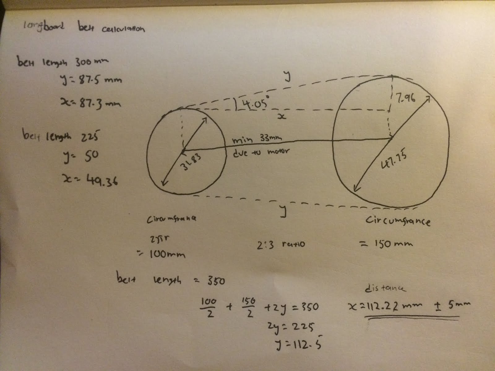
From the picture, one can tell that it was not going to be reliable. The idea was to create a two part mount so that i can freely adjust the angle. Another advantage of using this design was the ability to adjust the tension of the belt. Although this design prevented shaking in the X - Y direction, it could still come loose in the Z direction. Another downside of a two part system is that its less secure and caused a lot of oscillation. The mount was designed for a 300mm belt which should be 87.5mm apart between the motor and the centre of the truck.
 |
| My calculations |
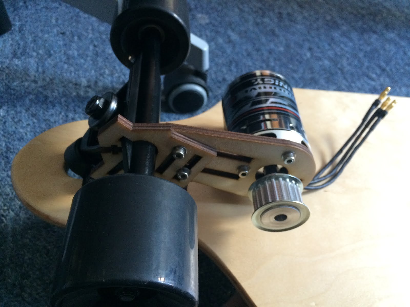
Soon a few modifications were made. I changed the belt length to have the motor at minimal distance apart. I ended up using a 225mm belt which i believed to be the optimal length. Upon realising the failure of using plywood, i needed to seek out an alternative. I stuck the my idea that i didn't want to change the existing structure of the long board so welding was out of the consideration. I decided to create a custom mount using my 3d printer to prototype a design. although 3d printing is relatively strong, it cannot withstand too much strain. I proceed to design my first 3d printed mount.
 |
| First 3d printed attempt |
I modelled the design from the plywood design but replaced it with PLA plastic printed at 100% infill. The design still incorporated a movable motor design for me to adjust tension. The design had a screw and bolt at the end to enable the mount to be firmly placed. It did its job when the motor was free wheeling, but would still move when significant force was applied to it. I decided to double the thickness of the print but keeping the design.
 |
| Second attempt at printing |
The second print was much stronger and i was not able to move the motor with my hand, I assumed that the mount was working. I then took it on a test drive. It worked for 30 mins before the mount failed and i lost tension in the belt. Not to mention that i hit a rock and it took a toll on the motor.
 |
| Motor after first ride |
In my defence, I wasn't paying attention to the stones as i was too focused on the long boards performance. As you can see, basically duct taped everything down, an engineers solution to moving parts. I knew i needed a new design for the motor mount, one that is stronger and will not slip. which takes me to my latest design.
 |
| Full truck mount |
I went all out and designed a two part mount which is bolted down by a 4mm bolt. The main structure is 100mm thick and the part protruding that hold the motor is 10mm thick.
 |
| With the motor fitted on |
The design ensures that the 4mm bolts are flush to the surface and are thread locked down. This was the design i used in my test drive.
The Main body
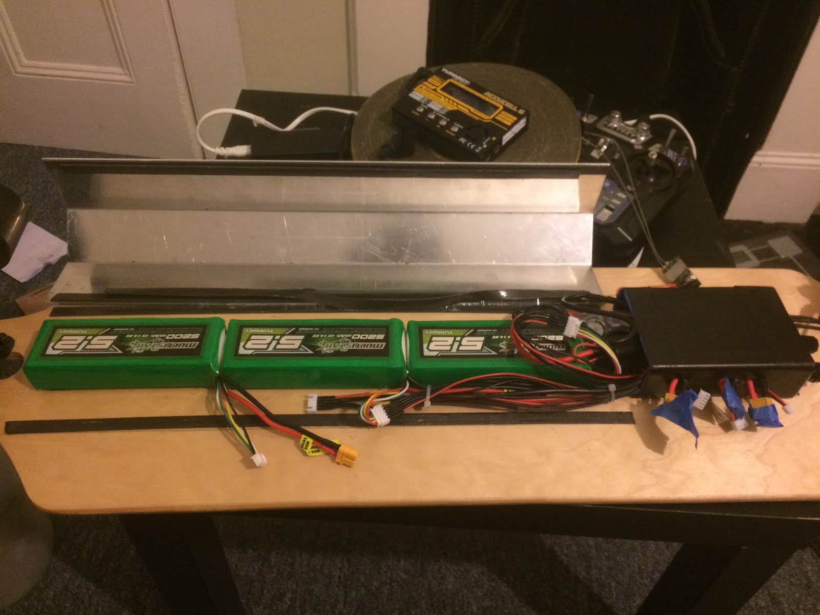
The lipo batteries and ESC where going to be underneath the board. to protect them, i needed a strong material as a guard for all my wiring and batteries. I got hold of some 2.5mm aluminium sheets. To be honest i was impressed on how strong it was. I had to use a band saw to cut it down to the size i wanted. Bending it however was the tricky part. I initially tried bending it with my bare hands which was a stupid idea since i couldn't even dent it. I tried hammering it into shape, but i still could not even bend it. I eventually got access to an industrial sized metal bending machine that eventually did the trick. After going through all that, i was certain it will be tough enough to protect the delicate LiPo batteries.
You can see the three LiPos and some extensions i used to wire everything up to the black box containing all the electronics and safety devices. I used industrial double tape to hold everything down. I applied one layer on the board and another on the metal Armour. If i needed to remove the tape, i would use isopropanol to soften the tape and use a chisel to remove it. I had to do it once as i found out i had a dead cell in one of my LiPos.
The Assembly
Below is my fully assembled board

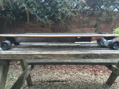

The assembly stage is always the best as it gives me the thrill of testing my creation when all is done. But i do feel sad because i always try and make my designs as neatly and as clean as possible before a test and they always return muddy and dusty.
The Test
The Main body
The lipo batteries and ESC where going to be underneath the board. to protect them, i needed a strong material as a guard for all my wiring and batteries. I got hold of some 2.5mm aluminium sheets. To be honest i was impressed on how strong it was. I had to use a band saw to cut it down to the size i wanted. Bending it however was the tricky part. I initially tried bending it with my bare hands which was a stupid idea since i couldn't even dent it. I tried hammering it into shape, but i still could not even bend it. I eventually got access to an industrial sized metal bending machine that eventually did the trick. After going through all that, i was certain it will be tough enough to protect the delicate LiPo batteries.
 |
| The super Armour |
 |
| The inside of the Armour |
The Assembly
Below is my fully assembled board


The assembly stage is always the best as it gives me the thrill of testing my creation when all is done. But i do feel sad because i always try and make my designs as neatly and as clean as possible before a test and they always return muddy and dusty.
The Test
I have done many test rides with this board at many stages and they always fail halfway and i would expect them to fail as i was finding aspects to improve. This test, i was confidant enough to ride by the pavements with other pedestrians which would be a true test of my ability to move, slow down, stop , avoid obstacles and judge what to do when unforeseen situation arises. I am very cautious of not just my safety but of those around me as well. Below is a video of one of my test rides. I did a few including top speed. I could not record that video as i needed to to hold the controller on one hand and my phone recording on the other.
I was able to make 5 trips on that stretch of road no problem. I Started at full battery and when i took the reading after the journey, the voltage had only dropped by 0.2V per cell.
Damage check
After the ride, i checked the board for damages. The chassis was fine other than being a bit dusty. the main damage that occurred was on the 3D printed part.
The damage was not caused by the test ride we saw in the video. It was caused when i attempted to go up a steep hill near to where i live although i manage to reach the top it damaged the mount. despite being damaged, it was still able to propagate me without the belt slipping. The main structure was still intact. The crack was due to the nature of 3D printing. As you know, 3d printing works by layers, and although i got high quality materials, I might be able to reduce the tension by reducing the motor and truck distance by 1-2mm. it will take some strain off the belt but still be within tolerable parameters.
So what Now
I still need to work on some things such as further improving the motor mount, incorporating my watch to work with the board such as monitor the voltages as well as acting as a key. Working on waterproofing the electronics is always something i can do to improve it. Then the final test.....
James and i are going to race from Bristol to bath. We will see which electric vehicle will triumph, it could also be down to the driver since he has beaten me at go cart twice now. Anyways, the race can only commence when he returns from the States.
Until then, i will be preparing for the big day.
I was able to make 5 trips on that stretch of road no problem. I Started at full battery and when i took the reading after the journey, the voltage had only dropped by 0.2V per cell.
Damage check
After the ride, i checked the board for damages. The chassis was fine other than being a bit dusty. the main damage that occurred was on the 3D printed part.
 |
| The toll it took |
The damage was not caused by the test ride we saw in the video. It was caused when i attempted to go up a steep hill near to where i live although i manage to reach the top it damaged the mount. despite being damaged, it was still able to propagate me without the belt slipping. The main structure was still intact. The crack was due to the nature of 3D printing. As you know, 3d printing works by layers, and although i got high quality materials, I might be able to reduce the tension by reducing the motor and truck distance by 1-2mm. it will take some strain off the belt but still be within tolerable parameters.
So what Now
I still need to work on some things such as further improving the motor mount, incorporating my watch to work with the board such as monitor the voltages as well as acting as a key. Working on waterproofing the electronics is always something i can do to improve it. Then the final test.....
James and i are going to race from Bristol to bath. We will see which electric vehicle will triumph, it could also be down to the driver since he has beaten me at go cart twice now. Anyways, the race can only commence when he returns from the States.
Until then, i will be preparing for the big day.